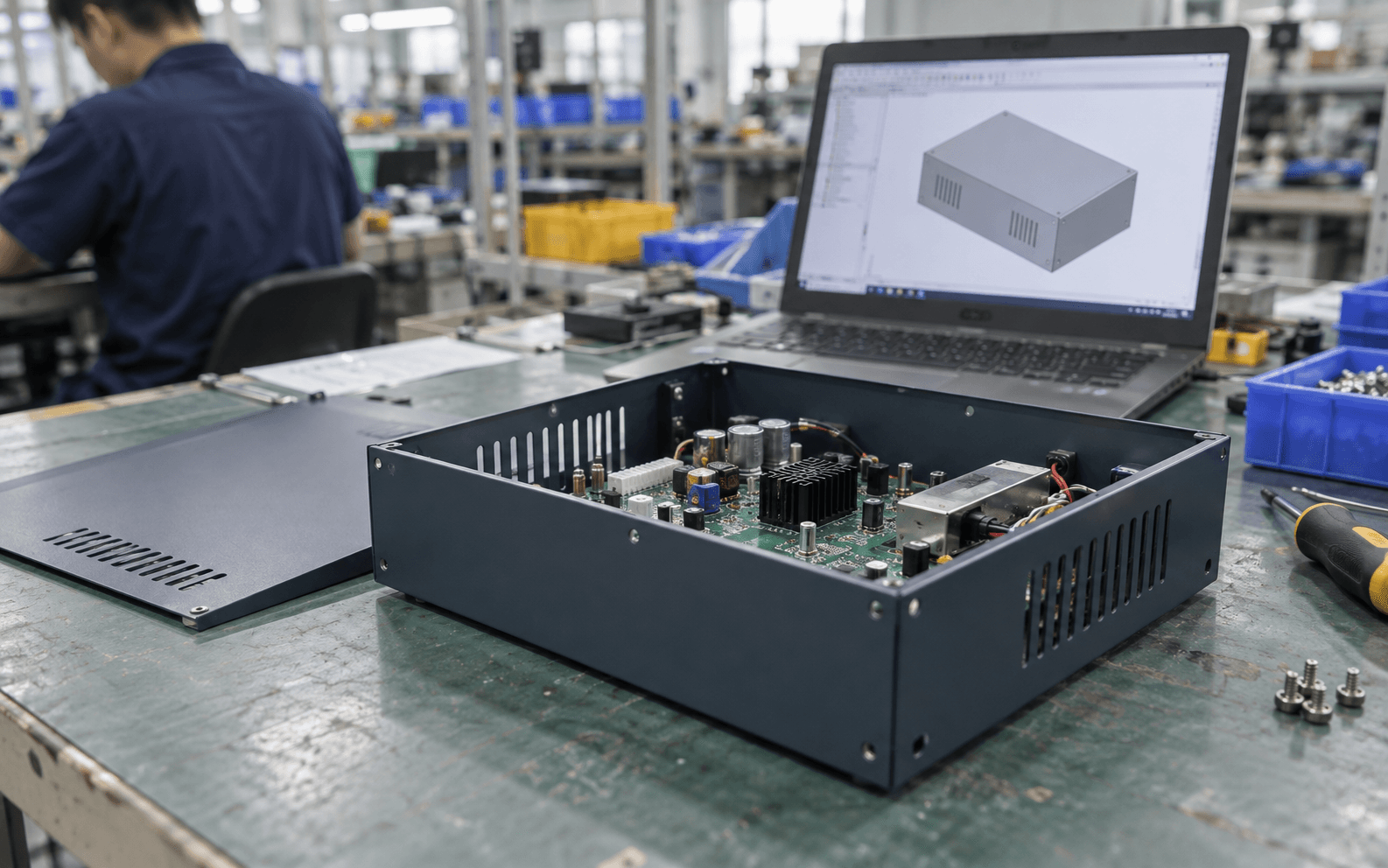
A folded metal box is one of the most practical enclosures for electronics, test equipment, kiosks and industrial products. It's strong, shields electrical noise, and needs no expensive tooling. But sheet metal has its own rules. A design that ignores them comes back with a long list of DFM comments, a higher price, or parts that don't fit.
This guide covers the rules that matter most for a first enclosure. The numbers below are common rules of thumb, not standards: every shop has its own tools, so always confirm with your supplier.
New to the process? Start with What is sheet metal fabrication?
Start with the right CAD approach
Use your CAD software's sheet metal tools rather than modelling a solid box and hollowing it out. Sheet metal tools:
- keep the thickness constant everywhere (the metal can't be thicker in one place),
- let you set a bend radius and bend relief, and
- can unfold the part into a flat pattern, which is what the shop actually cuts.
If your model can't be unfolded cleanly, it probably can't be made as drawn.
Pick a common structure
Most sheet-metal enclosures are built from two or three simple folded parts:
- Two U-shapes: a base folded up on two sides, and a cover folded down on the other two. Screws hold them together. Simple and cheap.
- Tray and lid: a tray folded up on four sides with corner gaps, and a flat or folded lid.
- Chassis and wrap: an internal chassis for circuit boards, with a separate outer cover for looks.
Fewer parts and fewer bends usually means a cheaper, more accurate enclosure.
Rule 1: one thickness, chosen early
Choose the material and thickness first, because many other rules depend on it. Thicker metal is stiffer but heavier, harder to bend tightly, and needs longer flanges. Steel enclosures often use roughly 1–1.5 mm; aluminum a bit thicker for the same stiffness (typical, confirm with your supplier).
Rule 2: bend radius about equal to thickness
Metal can't be folded to a razor-sharp inside corner; it bends around a radius. A common starting point is an inside bend radius roughly equal to the material thickness. Use the same radius on every bend if you can, so the shop doesn't need to change tools.
Some aluminum alloys (like 6061) crack on tight bends. 5052 aluminum bends much more easily and is the usual choice.
Rule 3: flanges must be long enough
A flange is the section of metal that's bent up. The press brake needs something to grip. If a flange is too short, the machine can't form it. A widely used rule of thumb is a minimum flange length of about four times the thickness. Short lips are one of the most common DFM comments.
Rule 4: keep holes away from bends
When metal bends, the area near the bend stretches. A hole too close to a bend line will distort into an oval. Keep holes and slots at least roughly two to three times the thickness (plus the bend radius) away from bends. If a hole must be near a bend, ask the shop to cut it after bending, which costs more.
Rule 5: add bend relief
Where a bend ends partway along an edge, the metal can tear at the corner. A small notch called bend relief stops the tear. Most CAD tools add it automatically; just don't delete it.
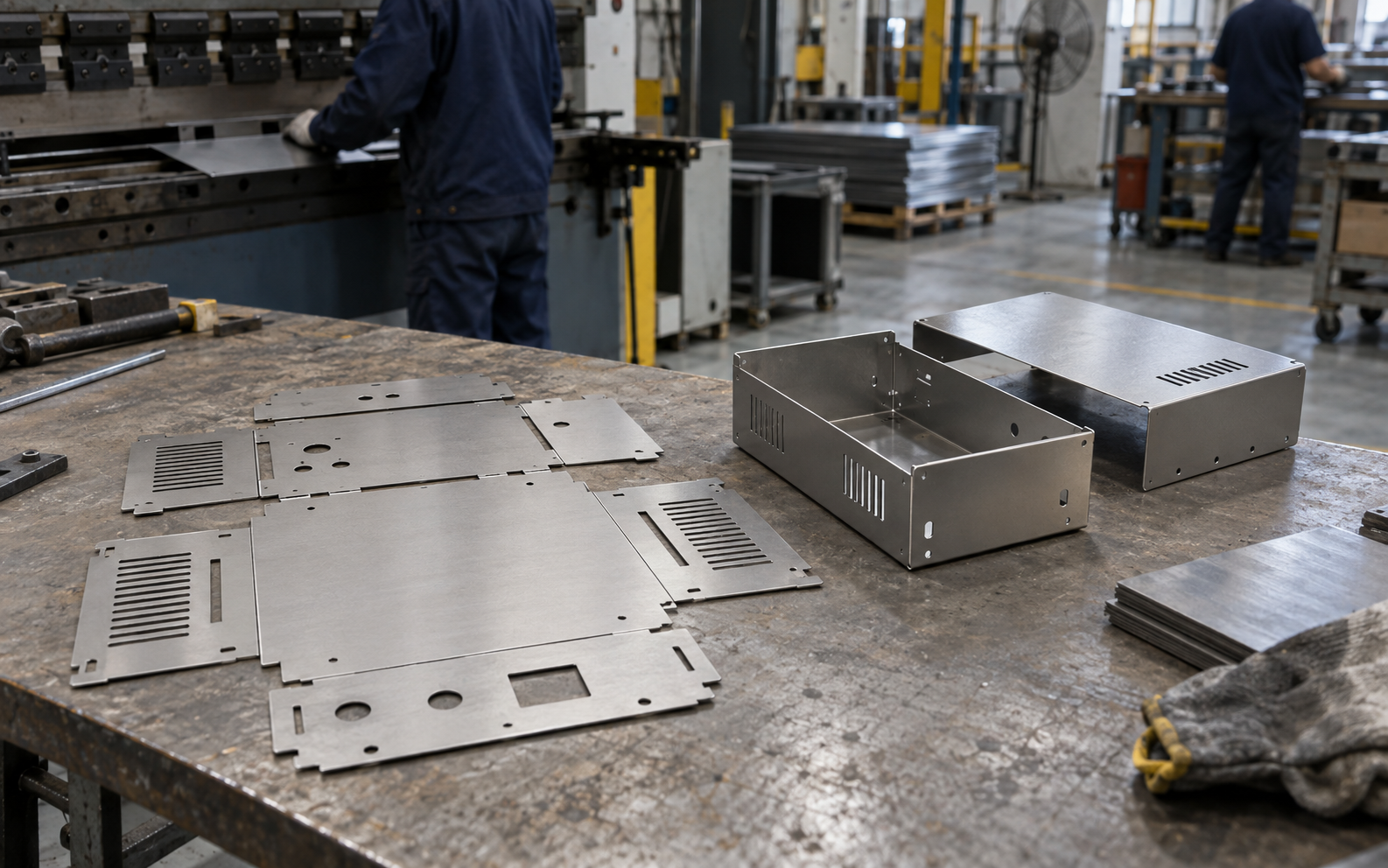
Rule 6: use pressed-in hardware for threads
Thin sheet is too thin to tap a useful thread into. Instead, use self-clinching fasteners: nuts, studs and standoffs pressed permanently into punched holes (often called PEM hardware, after a well-known brand). Specify the part number and which side it's inserted from on your drawing. Keep them away from bends and edges too.
For circuit boards, standoffs pressed into the base are a clean way to mount the PCB.
Rule 7: design vents and cut-outs for the cutter
- Vent patterns (rows of slots or holes) are cheap on a laser or turret punch. Keep the gaps between holes at least about the material thickness so the metal doesn't warp.
- Connector cut-outs should have a little clearance. Remember the powder coat adds thickness to every edge.
- Rounded inside corners on cut-outs are easier to cut cleanly than sharp ones.
Rule 8: think about finishing and grounding
Most steel enclosures are powder coated (a baked-on powder layer; see Anodizing vs powder coating vs painting). This matters for design:
- The coating adds thickness, so leave clearance on holes, slots and parts that slide together.
- The coating is an insulator. If the enclosure must be electrically grounded (connected to earth for safety or to reduce electrical noise), mark masked areas that stay bare metal, such as around a ground stud and on mating faces.
- Threads in hardware should be masked or plugged.
For colour, gloss and logo printing, see How to specify colour and finish.
Rule 9: realistic tolerances
Each bend adds a small variation, and errors add up across several bends. Sheet-metal tolerances are usually looser than CNC; many shops work to a few tenths of a millimetre on bent dimensions (typical, confirm with your supplier). Put tight tolerances only where they matter (for example, mounting holes for a PCB), and dimension them from the same reference edge.
What to send for a quote
- A 3D model (STEP) of each part and of the assembly.
- A 2D drawing per part with material, thickness, finish, hardware callouts, masking, and critical dimensions.
- A flat pattern DXF if you have one (the shop will still check it against their tools).
- Quantities, ideally at a few levels (for example 5, 50 and 500).
See How to write an RFQ for a full checklist.
A quick pre-send checklist
- Constant thickness, one material per part
- Same bend radius throughout
- Flanges long enough to bend
- Holes clear of bend lines
- Bend relief where bends end
- Hardware part numbers and insertion side marked
- Clearance for coating thickness
- Ground/mask areas marked
Keep reading
- What is sheet metal fabrication? (pillar)
- Anodizing vs powder coating vs painting
- How to specify colour and finish
- How to write an RFQ
Next steps
- Read the sheet metal hub
- Get quotes from sheet metal shops
- See the Design stage of the Path
- Glossary: 钣金 sheet metal, 折弯 bending
- Not sure where to start? Get an intro
Updated 29 September 2026